

In an earlier article we mentioned microwave concept for STLs. We mentioned elements on which we have now some affect: antenna dimension, transmitter energy, kind (and related loss) of transmission strains, and so forth.
Now let’s take into account facets of the microwave system over which you haven’t any direct management however can predict and work round utilizing collected data.
To overview, we have now realized that there is no such thing as a direct “loss” resulting from distance, it’s simply that as we transfer farther from the supply terminal, the sign is extra diffuse, and subsequently, you’ll be able to seize solely a smaller pattern.
Nonetheless, that’s loss in “free area,” which is nothing like the actual world. In our world, we have now atmospheric disturbances, temperature inversions (which have an effect on “Ok Issue,” to be mentioned later) in addition to interference from different sources, damaging sign polarity inversions when a path is over a physique of water, amongst different issues.
Among the many worst points an engineer could expertise with the microwave path, apart from gear failure, are interference from one other transmitter (generally at seemingly random instances); atmospheric results equivalent to tropospheric ducting, temperature inversions or polarity reversal of the wave entrance resulting from a reflective floor; and objects inserted into the trail with out prior data equivalent to a brand new workplace constructing.
So we open a toolbox of mitigation strategies which are confirmed to be efficient within the design of microwave techniques.
Forms of range
Frequency Variety: The concept right here is to have multiple frequency (or “channel”) within the system design (right here by “system,” I imply your complete assortment of transmitters, transmission line, antennas, receivers, filters, isocouplers, and so forth. that comprise your design as a complete).
Any such range, applied correctly, gives for robustness. If one channel is experiencing atmospheric anomalies, the opposite channel(s) will not be so affected.
Within the part of 47 CFR Half 74 that offers with guidelines for 950 MHz STL techniques, the channel unfold is probably going not sufficient to materially be of use for this kind of range (that’s to say, your complete channel unfold is prone to be affected by the self-same disturbance). Nonetheless, this could nonetheless be of fine use if there’s an interference problem which will have an effect on just one channel, and never one other.
Use of a completely totally different band, equivalent to 6, 11 or 23 GHz together with a 950 MHz band radio, might be of super profit by advantage of frequency range (this is also a type of technological range, to be lined later).
Hawaii suffers from periodic damaging interference throughout army RIMPAC actions, which result in unusable 950 MHz hyperlinks. The “value of freedom,” we’re advised. On this case, a number of 950 MHz channels are affected.
House Variety: Right here, the purpose is to separate two obtain antennas in such a way as to obtain the transmitted sign by way of a number of paths with some vertical separation. Empirically, a vertical separation of some 200 wavelengths has confirmed efficient. It simply so occurs this works out to about 200 toes at 950 MHz. So, when you have a obtain antenna (which we’ll name the “essential antenna”) at 700 toes AGL on the tower, then one other antenna (“aux. antenna”) is perhaps at 500 toes of elevation.
I had such an association in Orlando, which carried out very effectively throughout early morning temperature inversions throughout which the transmitted sign was diverted downward. I’d observe the receiver sign related to the principle antenna start to drop quickly whereas on the identical time, the obtained sign of the receiver related to the aux. antenna would rise.
On this case, the RSSI as indicated on the receiver related to the principle antenna, which usually would hover round 1100 µV, would drop beneath 200 µV! This type of range labored very effectively on this system. We’ll talk about the reason for this shortly.
Technological Variety: This technique is my private alternative for virtually final robustness. Right here, we combine applied sciences to attain virtually 100% reliability.
A number of decisions can be found to us in 2023. For instance, we are able to use a 950 MHz STL and an audio over IP machine equivalent to an Intraplex IP100/200 or a Comrex Bric. An alternative choice is a 6 GHz knowledge hyperlink (utilizing an IP200 because the audio codec) in addition to a 950 MHz hyperlink (a type of frequency range mentioned above). Additional, devoted fiber from the studio to the transmitter web site is an virtually final answer.
From a fault tolerance standpoint, if the redundant, numerous techniques every have “5 nines” reliability or 99.999% uptime, this implies the chance of failure is 1–0.99999 or 0.00001.
This means the chance of each techniques failing on the identical time is a distant 0.0000000001 or 1 in 10 billion.
Propagation and path
Now let’s concentrate on propagation and the trail itself.
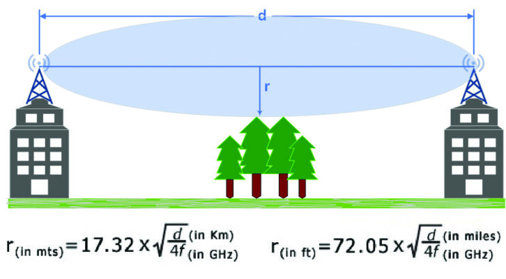
Normally, we want a transparent, line-of-site path from the microwave transmitter to the receiver antenna (away from obstacles). We decide this utilizing a terrain profile through the use of Google Earth or different appropriate software program. From this we are able to plot the “Fresnel Zone” (pronounced “Fray-nell”). See Fig. 1.
The system for calculating the Fresnel Zone is:
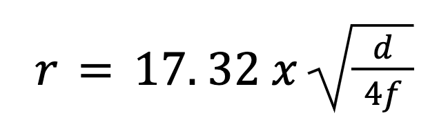
- r = radius in meters
- d = distance in km
- f = frequency in GHz
Sometimes, 40% intrusion by an object (this was empirically derived) into the Fresnel zone is suitable, so one can use 0.6 as a relentless multiplier. Any additional intrusion into the zone is taken into account a grazing path. If below these circumstances the trail has line of web site contemplating the intrusion, add 6 dB to the free area attenuation to compensate.
Reflections and Brewster’s angle
It’s well-known that microwave paths that traverse our bodies of water (lakes, bays, and so forth.) might be problematic because of the incident wave placing the water floor and thence being mirrored out of section or reversed in polarity. A bigger fade margin and a type of range are sometimes the one treatments out there to the design engineer.
Brewster’s angle is a complicated subject, however for our functions there exists an angle at which the incident wave is partially refracted into the water and polarized within the mirrored wave due to the distinction in density of the air/water interface. This may trigger a wave entrance to the obtain terminal being compromised by a polarized wave not of the identical polarity as that of the transmitted sign.
Ok issue and “Flat Earth”
Ok issue is a relationship of the radio horizon to the true earth radius on account of tropospheric bending and usually thought of to be 4/3 or 1.33. the gap below these situations is given by:
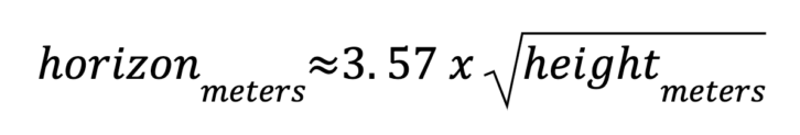
Nonetheless, normal isn’t at all times the case. Throughout temperature inversions through which the overlying air layer is hotter and subsequently much less dense (widespread on summer season early mornings after the earth has cooled greater than the overlying air), Ok issue can turn into 1.00, which is named the “flat earth situation” through which the wave entrance can journey for a really lengthy distance.
This phenomenon can also result in FM stations lots of of miles away booming into your market, inspiring your PD, OM or GM telling you that there’s “one thing incorrect with our sign” or “The station in Colorado have to be working ‘tremendous excessive energy,’ name the FCC.”
Typically these points clear up round 10 a.m. after the solar warms the bottom and atmospheric situations normalize. I skilled this notably in Central Florida throughout the summer season months.
Knife-edge diffraction
Once I was working in Southern California just a few years in the past, we had a web site on a windfarm in Tehachapi (wind generators by the lots of) to which the earlier engineer tried a 950 MHz “shot” from the Mojave “essential studio.”
No manner within the blue blazes would an precise engineer even have tried this technique given the terrain blockage (see Fig. 2). But in opposition to all odds, it labored after a style; the RSSI as indicated by the receiver would range wildly from 150 to 300 µV constantly (consider a VU meter), however by working the STL system in mono, the system produced a touch usable audio supply.
The one believable rationalization I and my educated colleague Doug Irwin may give you is the phenomenon of knife-edge diffraction.
Fig. 3 is the idealized depiction of a knife-edge diffraction state of affairs. This is identical phenomenon that means that you can hear sound from across the nook of a constructing (even in absence of reflective surfaces (keep in mind, 1 Hz to past X rays are all on the EM spectrum).
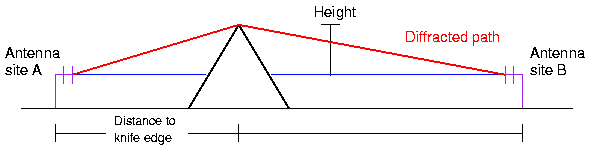
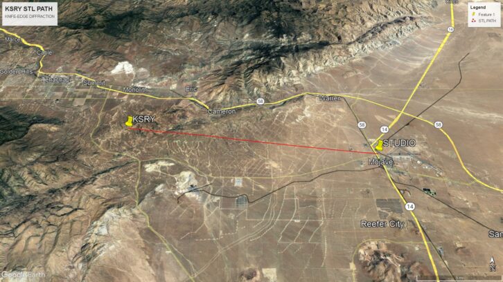
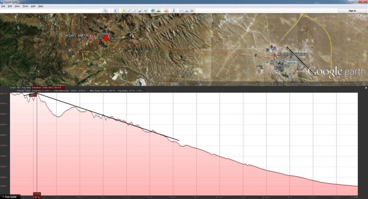
Fig. 4 reveals the KSRY path aircraft view.
Notice that the STL transmitter in Mojave is on the excessive proper of the illustration and the KSRY web site (receiver) is on the excessive left. Notice the “knife edge” peak lower than a mile from the receiver. That is effectively past a grazing path!
Conclusion
The right design of a microwave system requires some minimal data of the matters we’ve mentioned. Luckily, a mess of on-line calculators exist to help you. Even with the help of such calculators, you can also make higher use of such helpers when you have a fundamental understanding of your complete system.
[Check Out More of Radio World’s Tech Tips]